We take our time when nesting complex parts for the CNC (Computer Numeric Control) machine. There are many factors and considerations that must be followed to not only achieve the correct parts that the customer needs, but to also protect the CNC from failure.
The parts below are to be cut from a 12-inch-thick billet of Mass Ply. These parts are 6.5 feet long and three feet wide. The parts have presented many challenges for the large saw. On the angle cuts, the saw will bog down and cannot leave the kerf. That leaves the operator starting and stopping continuously to complete the longitudinal cuts. The cross-cuts must be changed so that they are moving from y-positive toward y-negative, so that the saw can lift from the kerf.
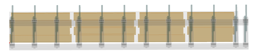
The image below is the view within Lignocam that generates the code for the Weinmann CNC. The minimum distance we have for our Weinmann CNC Table is 52 inches between sawhorses. This displays that the small parts are supported by at least two of the sawhorses that the billet will be sitting on.
Some Nesting will result in tooling failure. If a gap is too large between multiple geometric pieces, it can result in the Router Bit getting pinched in between the kerf and drop. This is the case for thick billets of Mass Ply since the tool is primarily at its farthest reach of the flute length. The tooling setup on the Weinmann CNC includes an 18 Position Rotary Tool changer. The maximum thickness of Mass Ply that we can currently route would be a seven inch thick billet.
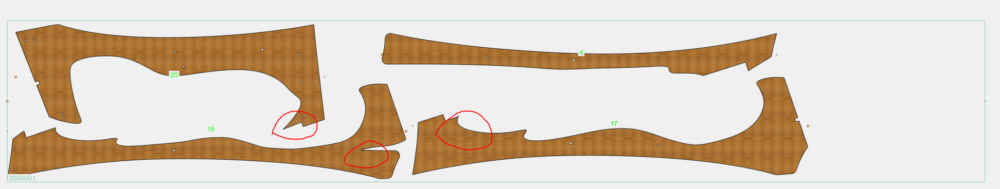
Kerf tolerance for the tooling is a huge factor when nesting parts with unusual cuts. These parts are cut from two inch thick Mass Ply and have a small radius the tooling must follow. The highlighted area with the red circles will dictate what tool can be chosen to achieve the cuts. These factors must be followed, or the parts will not match the shop drawings. With our machine setup the only tool that we could use was the 16 MM router bit that we have tooled in position number one of the turret.
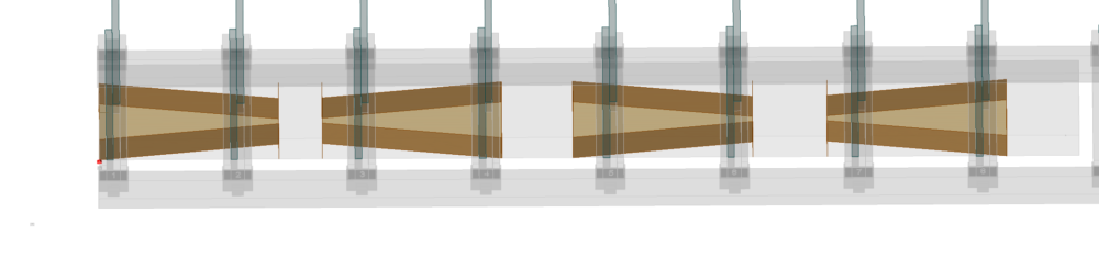
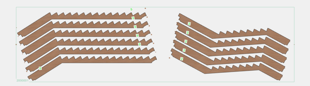
Nesting stair treads with the landing attached posed concerns with choosing the correct angle to get the most longitudinal grain from the cuts. These were set at a 32-degree angle to allow most of the minor force to be seen in the landing and leave the major force grain in the tread itself.
The gap between parts was set to three inches to allow minimal to little drop between parts so that they would not collide with the tooling while cutting.
When dealing with complex parts, always make sure to communicate with the designer any potential errors that may come up during the importation and programming of the files. At the end of the day, teamwork and clear communication among everyone involved will make for a smooth outcome and correct parts.
Subscribe
We’ll send you a notification when a new story has been posted. It’s the easiest way to stay in the know.