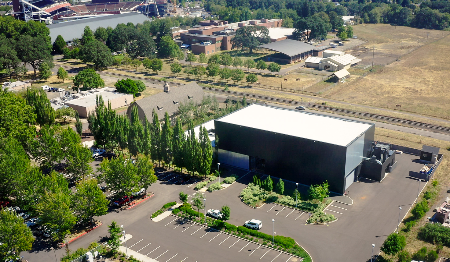
The Oregon State University (OSU) Advanced Wood Products Laboratory is the site for a slew of exciting projects in the mass timber and wood products industry. While the lab is a source of testing for modern manufacturing technologies and development for environmentally friendly materials, it also helps push the limits of current building codes. One big way of pushing the codes is by, well, pushing buildings — mass timber buildings to be precise.
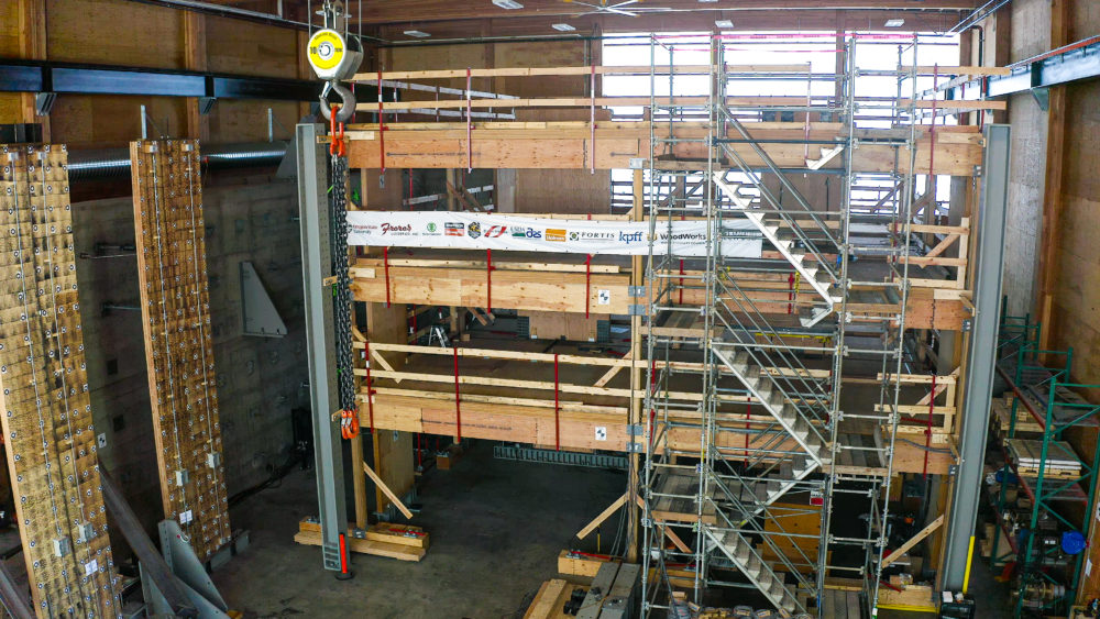
Researchers at OSU have been hard at work over the last several months assembling and testing a code-pushing building. The test subject is a three-story, 30 foot tall building made entirely from veneer-based products; including our Mass Ply Panels (MPP) in the walls and floors. The purpose of the test is to validate many common designs for mass timber and to put several new systems to the test.
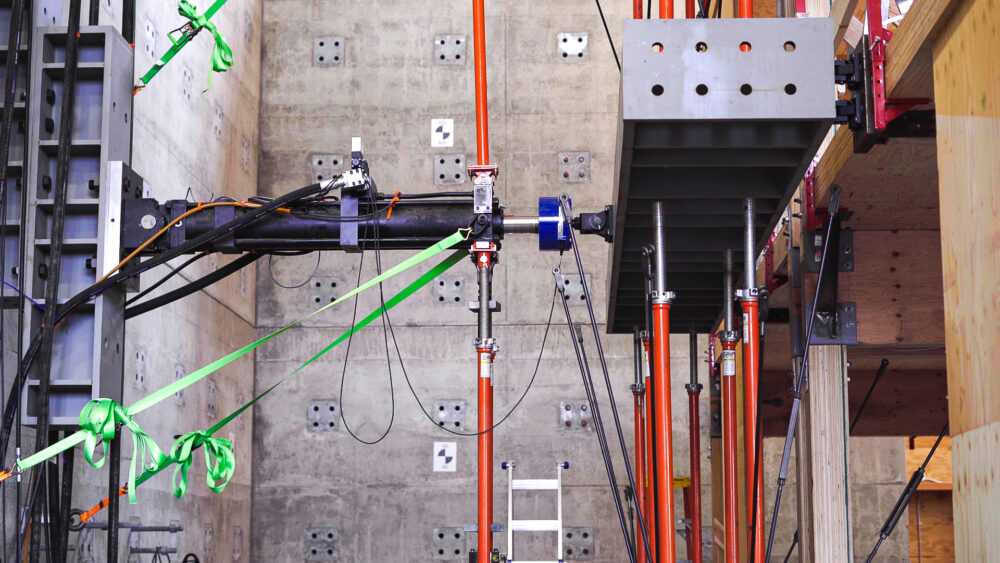
Many of the building parts to be tested are what we call “lateral systems.” Like the plywood on the side of a house, lateral systems help keep a building from rocking back and forward during a windy day, or when the ground beneath your house decides to get up and go for a walk (an earthquake). Rather than using wind or tectonic plates, this test will simulate those loads using an “actuator.”
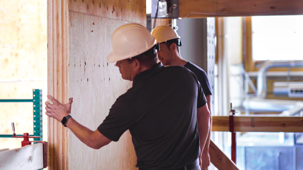
MPP shear walls will be the first element tested in the building. To understand how much the walls help with resisting lateral forces, researchers must first understand how much resistance the building has naturally. In this case, how the building would do without walls.
In mid-August of 2022, researchers tested the building with only floors, beams, and columns in it. To set a baseline, the walls were initially left disconnected from the floor of the building. By pushing the building sideways, more than one percent of its height (about 4 inches at the top), researchers could determine how stiff the frame of the building is without relying on the walls.
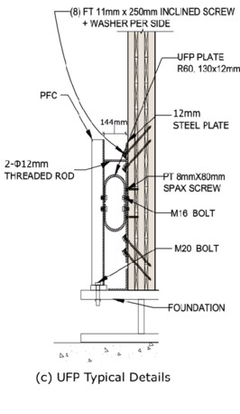
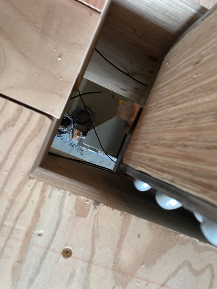
With Phase 0 complete, the next step is to attach the shear walls to the floor, here called the diaphragm. The diaphragm will transfer the building’s own weight into the shear walls causing them to rock back and forward. Imagine this motion like you’re holding a book, cover facing you, resting on a table. Now rotate the book like you’re turning left and right in a car. Just like how the book rocks from one corner to another, these shear walls behave the same way. As the wall rocks, it bends a piece of ‘U’ shaped metal connected to the foundation called a UFP.
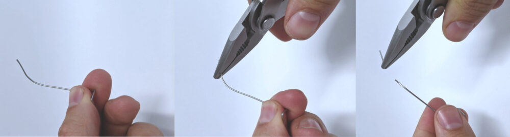
It’s not entirely clear how these UFPs work. Why are these necessary? Here’s a small demonstration you can perform right now at your desk to understand why they’re useful. Take a paperclip and straighten it out. Press the paper clip to your skin and notice how cool it is, for example to your cheek bone. Next, grasp the paper clip and bend it back and forward repeatedly in the same spot. Continue to do this until it breaks. Now take the paperclip and place the newly broken piece against your cheek bone again. The spot where the paperclip broke should be considerably warmer. Congratulations, you just experienced the beauty of plastic deformation!
Buildings use plastic deformation to help remove energy from the moving building by converting the moving energy into heat energy. By causing permanent damage to the metal plate (i.e. plastic deformation), you have a way to make sure that energy doesn’t go elsewhere into the building. For example, making sure that energy doesn’t go into tipping over your bookshelves. The metal in these connections is made to experience a LOT of plastic deformation and to last at least a little longer than the paper clip at your desk.
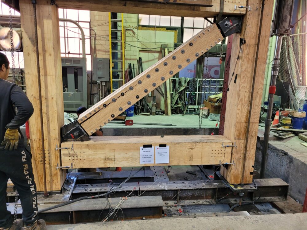
With Phase 0 complete and Phase 1 on the horizon for November 15, 2022, we’re eager to look ahead for other revolutionary systems, such as the Buckling Restrained Braced frame (BRB). This type of system has traditionally been left for concrete and steel because wood generally doesn’t get rid of energy the same way steel does, like heat and bending. However, by teaming up wood and steel, these BRB systems allow for a very effective lateral system that saves both a lot of weight and wood fiber.
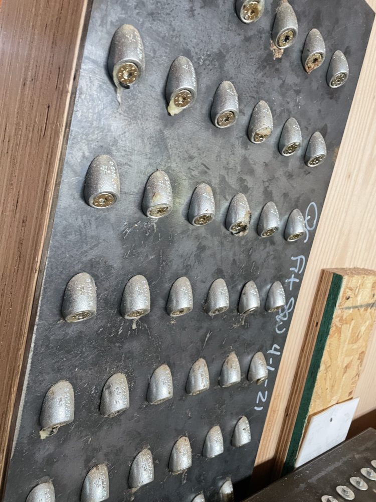
Much in the same way a UFP gets rid of energy through bending and heat, these steel braces get rid of energy through “buckling.” If you’ve ever leaned a little too hard on a long walking stick and had it bend under your weight, then you’ve experienced buckling. Buckling happens when we compress or “squeeze” a long, slender piece of material which causes it to bend in the middle.
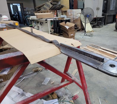
Now if you had a friend hold that same walking stick in the middle and prevent it from moving, you’ll notice it becomes a lot harder to buckle. Not only that but, by holding it in the middle, when it does finally buckle it will bend in two spots — not just one. Now imagine holding it in ten spots, or a hundred spots. Once we sandwich the metal between a couple pieces of MPP, this will cause the strap to buckle many times and create a very wavy surface as it buckles repeatedly. This buckling causes permanent damage which also dissipates energy just like the UFP.
There’s a lot to look forward to at the OSU Advanced Wood Products Laboratory in the coming months. We’re excited to see how MPP can be used in new and exciting ways to drive forward building innovation and pave a path for more sustainable building design.
Subscribe
We’ll send you a notification when a new story has been posted. It’s the easiest way to stay in the know.